 English
 Türkçe
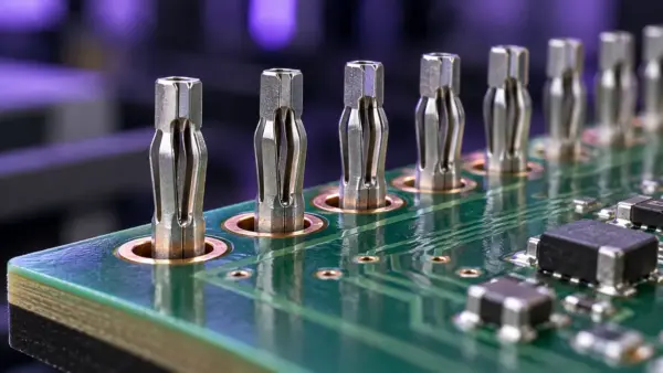
Press-fit technology is a solderless interconnection method that provides electrical contact and mechanical retention by applying controlled force to insert specially designed contact pins into plated through-holes (PTHs) in a printed circuit board (PCB). It is an important option for solderless PCB connections, particularly in applications where connection quality, assembly conditions, and production records must be evaluated together.
However, the press-fit process involves more than pressing a connector into a board. Press-fit pin design, hole specifications, insertion force, insertion speed, and the PCB support fixture must be considered together. For manufacturing teams, the central question is not only how the connection is formed, but also how correct assembly will be verified on every board.
How Does Press-Fit Technology Work?
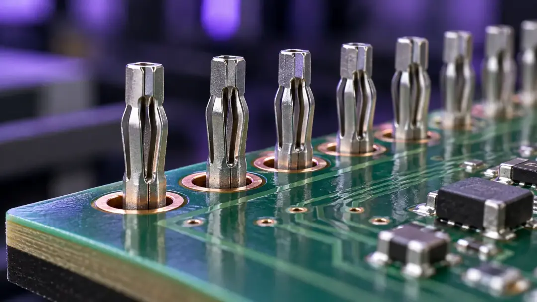
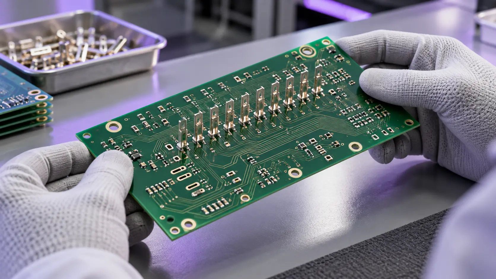
Press-fit is a solderless interconnection technology in which contact pins with suitable geometries and tolerances are inserted into properly plated PCB holes using controlled insertion force. With compliant pins, the contact section undergoes controlled elastic deformation and applies contact pressure to the inner surface of the hole.
Compatibility Between the Press-Fit Pin and Plated Through-Hole
Press-fit pins may have solid or compliant contact sections. A compliant pin is designed to deform as it enters the hole and to apply pressure to the contact surface. This helps establish electrical contact and mechanical retention. The press-fit pin and the PCB’s plated through-hole should therefore be evaluated as a single interconnection system rather than as independent components.
For this reason, selecting a connector is not enough during the design stage. The connector’s PCB requirements must also be incorporated into the board fabrication specification. Using the same technical requirements across purchasing, PCB fabrication, and assembly gives all teams a common starting point for the transition to volume production.
Why Is Press-Fit Preferred as an Alternative to Soldering?
The primary distinction of press-fit technology is that it does not require a soldering operation to create the connection. In suitable designs, connector assembly can be planned as a separate operation after the board’s other assembly steps. In addition to press-fit pin and hole specifications, insertion depth and speed also affect connection performance.
This approach requires different questions to be considered when evaluating production flow. At which stage will the connector be installed? How will components on both sides of the board affect fixture design? At which station will post-assembly inspection be performed? The value of choosing press-fit becomes clearer when these questions are considered together.
When deciding between soldered and press-fit connections, it is more useful to compare product design, production volume, inspection requirements, and the overall process structure than to focus only on machine cycle time. Not every connection design is suitable for press-fit. For a new product, the connector manufacturer’s application instructions, PCB fabrication capabilities, and assembly trials should be reviewed together.
Why Is Compatibility Between the Press-Fit Pin and PCB Hole Plating Important?
In an application that uses compliant press-fit pins, the pin’s compliant section and the PCB hole specifications must be compatible. Indicating only the hole location on the board drawing does not provide all the information required for assembly.
Finished Hole Specifications and Board Revisions
The finished hole is the hole obtained after drilling and plating during PCB fabrication. The hole information in the design file must therefore be evaluated together with the surface encountered by the press-fit pin during assembly. Press-fit pin geometry, surface finish, and hole requirements should be defined according to the application instructions for the relevant connector.
A practical checklist for use by project teams may include:
- The exact connector part number and current assembly instructions
- The manufacturer’s finished hole requirements
- How the PCB manufacturer will verify these requirements
- Matching the board and connector revisions
- An acceptance plan for moving from trial assembly to volume production
The checklist should also explain how a change made by one supplier will be communicated to the other teams. For example, the project can define in advance whether the existing press-fit recipe must be reevaluated when the board revision changes. This prevents the production team from having to identify changes based only on the appearance of the parts.
How Should Insertion Force Be Evaluated?
Insertion force is the force applied as the press-fit pins enter the holes. The required force is evaluated according to the connector design, number of pins, and relevant PCB characteristics. Values stated in the assembly instructions for one connector should not be transferred directly to a different connector.
The rigidity of the press, tooling, and fixture must be considered together with proper alignment and controlled insertion. Supporting the board beneath the connector and providing adequate clearance for press-fit pin protrusions on the underside are also part of the application design. The support geometry should be prepared according to the product’s own assembly instructions.
When selecting a machine, the maximum press capacity must be distinguished from the insertion force required by the application. A high-capacity press does not, by itself, guarantee correct assembly. Control capabilities, tool access, working area, and the product changeover method should also be discussed during project evaluation.
What Does the Force–Displacement Curve Show?
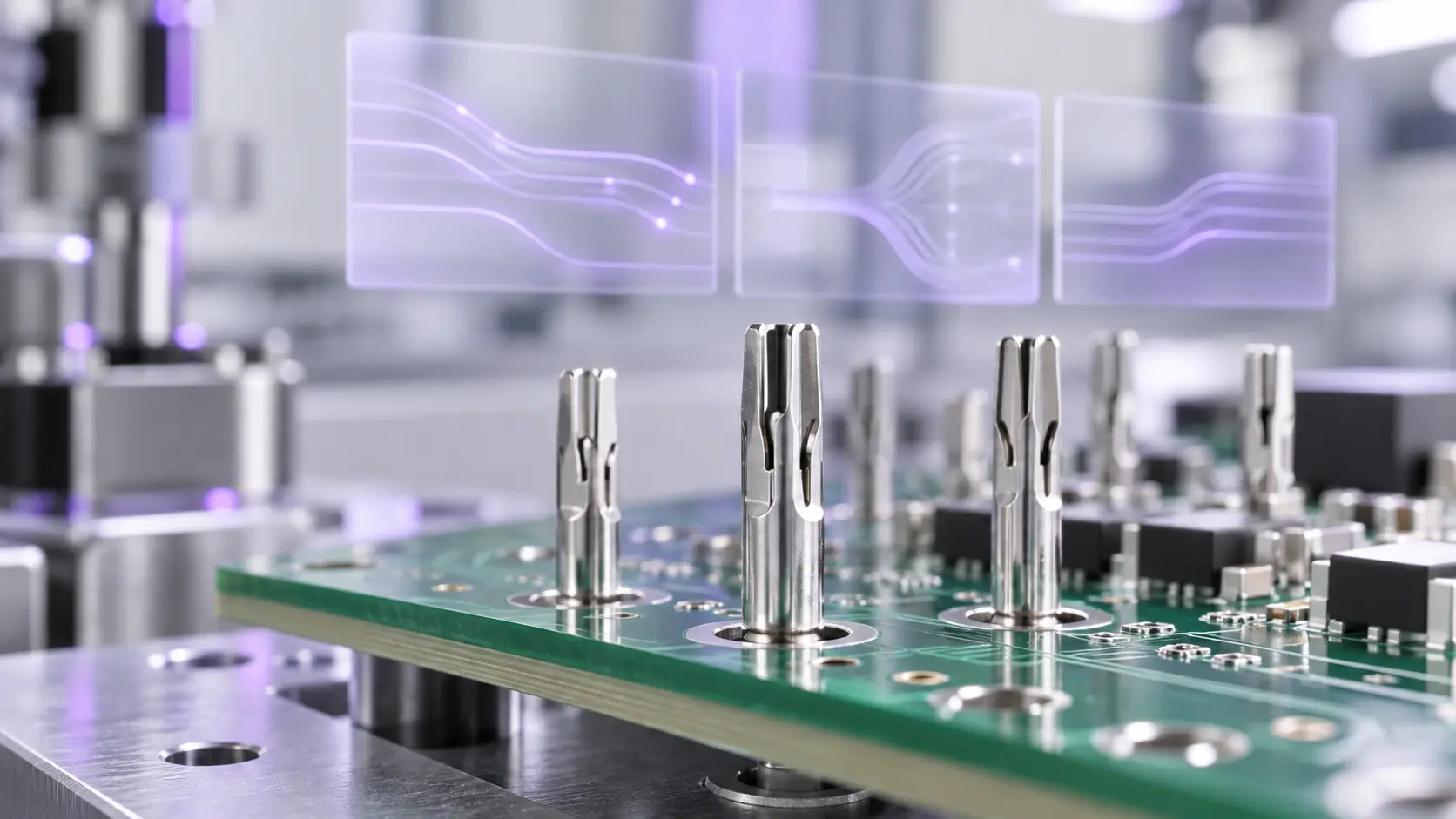
A force–displacement curve shows how the force measured throughout the insertion process changes in relation to the travel of the press tool. Evaluating this curve against previously validated acceptance limits helps monitor the insertion process and identify potential assembly deviations.
On the Kurtz Ersa VERSAFIT 500, force and travel data can be monitored through configurable evaluation areas and tolerance limits. This structure allows the assembly cycle to be compared with the defined process conditions.
Acceptance Windows and OK/NOK Evaluation
During production preparation, acceptance limits should be linked to the results of trial builds rather than being based only on a curve that appears correct. Acceptable assembly samples, investigated deviations, and inspection results can be used in the same evaluation. The objective is to establish an application-specific decision method rather than expecting the operator to interpret every curve.
An OK result from the machine indicates that the parameters measured during the relevant insertion cycle met the predefined acceptance criteria. A NOK result indicates that a deviation from the defined process limits was detected. This evaluation does not replace the product’s electrical and mechanical validation tests. It should not be interpreted as independent proof of reliability throughout the product’s entire service life. A total force curve is also not equivalent to an inspection that measures the condition of each press-fit pin individually. Product-specific electrical, mechanical, and other validation requirements must be addressed separately in the quality plan. Test, control, and inspection systems suited to the board’s requirements can be evaluated as part of this plan.
How Should the PCB Support Fixture and Press Tool Be Planned?
The PCB support fixture should be treated as a fundamental part of the application rather than as an accessory to the press-fit machine. Board layout, components on the underside, press-fit pin exit areas, and access for the press tool must be reviewed together.
Support for Components and Protruding Press-Fit Pins
Rather than designing the fixture only around a bare board, it is useful to examine the board in its actual condition at the assembly stage. The evaluation can include which components are already on the board when the connector is installed, how the operator positions the board, and whether incorrect orientation is possible.
How a fixture prepared during the prototype stage will be used in volume production should also be considered. A simple method can be established for identifying, storing, maintaining, and matching the tool with the correct recipe. On a line with frequent product changeovers, this preparation can be as important to daily operation as the machine’s technical capacity.
How Can Press-Fit Process Traceability Be Established?
Press-fit process traceability is intended to make it possible to review which board was assembled under which conditions. The process should begin by defining the records that are actually required. The same scope of data is not necessary for every project.
Records that may be considered for an application include:
- Board or product serial number
- Assembly recipe and recipe revision
- Assembly time and station information
- Force–displacement curve
- Cycle evaluation result
- Processing record for a nonconforming product
MES Connectivity and Using Production Records
How these records will be matched with the manufacturing execution system, how long the data will be retained, and how data-access responsibilities will be assigned should be discussed during the project stage. Kurtz Ersa’s published information for VERSAFIT ONE identifies traceability and MES connectivity as options. Whether these functions are included in the quoted configuration must therefore be clarified separately.
Laser marking, traceability, and MES solutions can also be included in the production project to connect product identity with the assembly record. The important point is to match the identity on the board with the correct press-fit cycle.
Another important consideration is the procedure to be followed after a NOK result. The project can define how the product will be segregated, how it will be sent for investigation, and who will be authorized to decide on rework. Collecting records becomes more valuable to production when the decisions to be made from those records are clearly defined.
How Is Press-Fit Evaluated in Automotive, Electric Vehicle, and Other Applications?
Automotive and Electric Vehicle Electronics
Automotive electronics is one of the fields in which press-fit connections are used. Evaluation of a new automotive project should begin with the product’s connection design and validation requirements. Selecting a connector or machine based only on the industry is not sufficient.
In electric vehicle electronics, the function of the connection must be clearly defined. When evaluating connector assembly on a control board, signal transmission, board layout, and subsequent test steps can be reviewed together. The specific requirements of the design prepared for an electronic control unit, power conversion system, or other subsystem should form the basis of the evaluation.
Charging Infrastructure and Power Electronics
In charging infrastructure, motor drive, and power electronics projects, control connections must be distinguished from power connections. The term press-fit does not, by itself, indicate the current-carrying capacity or operating conditions of a connection. The appropriate press-fit pin and board design must be selected according to the connection’s actual function.
During the project meeting, the circuit associated with the connector on the board can be identified. Requirements for drive control, measurement, or communication connections should be considered separately from the requirements of the main power path. This distinction helps turn equipment evaluation from a general industry discussion into a specific assembly application.
Defense and Industrial Applications
The same evaluation approach can be used for suitable connection designs in defense and industrial electronics projects. Environmental conditions, maintenance expectations, supply continuity, and acceptance criteria should be taken from the project requirements. The suitability of a specific press-fit application must be evaluated for the individual product.
Tooling management and documentation also require attention for products manufactured in low quantities but continued across different revisions. For a board that returns to production after an extended period, the fixture, recipe, and inspection plan to be used must be clearly identified. You can explore Sinerji’s electronics manufacturing approach across different applications on the Clients and Testimonials page.
What Information Is Needed When Selecting a Press-Fit Machine?
Defining the product’s technical characteristics and manufacturing requirements before selecting a press-fit machine makes it easier to compare different solutions. The PCB drawing, connector assembly instructions, components that will be present on the board during insertion, and target production volume are the essential inputs for this evaluation.
Production Volume and Automation Requirements
Machine selection should take into account product variety and the required level of automation. It must be determined whether a single product will be manufactured, how frequently production will change between different boards, and whether boards will be loaded by an operator or automatically. Integration with the existing production line, changes to press tools, selection of product-specific process parameters, and product identification must also be evaluated.
When comparing proposals, it is important to request a solution for the same product and production conditions from every supplier. Clarify whether the stated cycle time includes loading and unloading, which fixtures and press tools are included in the proposal, which traceability features are provided, and which commissioning services are covered. This makes it possible to evaluate how well each solution meets your manufacturing requirements.
A Checklist for Equipment Evaluation
The table below can be used to compare different press-fit systems against the same application. The requirements of the board and connector to be manufactured should form the starting point of the comparison.
| Evaluation area | Question to ask | Information to clarify |
|---|---|---|
| Product compatibility | Which boards and connectors will be assembled? | PCB drawing, part number and assembly instructions |
| Force and motion control | How will the application be controlled? | Force range, speed, depth and evaluation method |
| Tooling and fixtures | How will the board be supported? | Lower support, press tool, and component clearances |
| Product changeover | How will production change over to a different board? | Tool changes, recipe selection and first-piece inspection |
| Line integration | How will the station connect to the production flow? | Loading, unloading and interaction with adjacent stations |
| Traceability | Which data will be recorded? | Product identity, cycle result, curve and data connectivity |
| Commissioning | How will production readiness be approved? | Sample run, acceptance plan, and operator preparation |
How Should the Transition from Trial Assembly to Volume Production Be Prepared?
The initial sample run should not be used only to demonstrate that the connector can be inserted into the board. The information to be recorded and the method for evaluating the assembly can be determined in advance. The board revision, connector part number, tooling, and recipe can all be documented in the same trial record.
It is useful for manufacturing, quality, and design teams to review the results together. The design team can explain the product’s acceptance criteria, the manufacturing team can evaluate loading and cycle flow, and the quality team can define how inspections will be performed and how nonconforming products will be managed. In this way, a successful trial assembly becomes a working method that can be used for volume production.
Operator Preparation and Work Instructions
Product changeover can also be tested before volume production begins. The operator’s selection of the correct fixture, retrieval of the recipe, and completion of the first-board inspection can be reviewed as part of the daily workflow. Converting these steps into clear work instructions makes preparation easier when the same product returns to the line. Any issues that remain open at the end of the evaluation can be documented together with the responsible parties and completion criteria.
Operator preparation should cover more than starting the machine. Correct board loading, recipe verification, and segregation of nonconforming products are also part of the daily workflow. Visit the Sinerji Academy page to explore electronics manufacturing training.
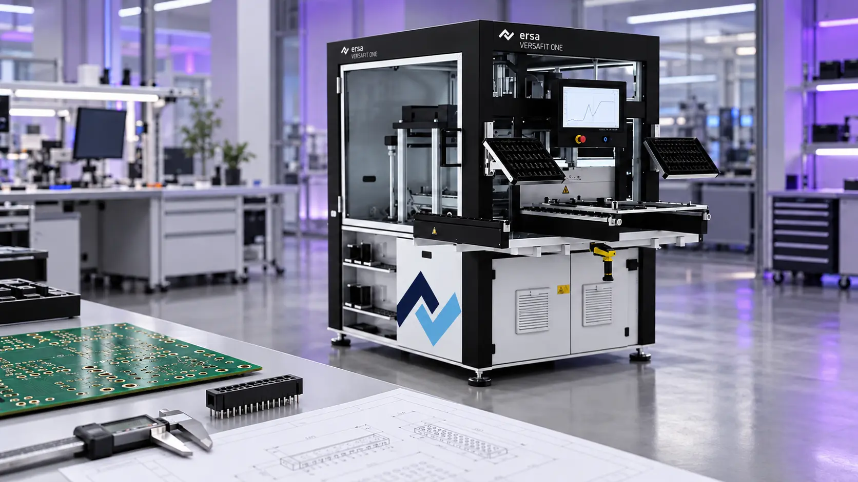
Press-Fit Process Control with Kurtz Ersa VERSAFIT
Kurtz Ersa, one of Sinerji’s solution partners, develops electronics manufacturing equipment and automation solutions. The VERSAFIT family offers systems for teams that want to manage press-fit connector assembly as a controlled production step.
VERSAFIT ONE: A Semi-Automatic Production Approach
The VERSAFIT ONE is a semi-automatic solution in which the board carrier is loaded manually and the insertion movements are performed by the system. Cycle results can be monitored by evaluating force–displacement data. Options such as traceability and MES connectivity should be addressed separately within the quoted configuration.
When evaluating this type of system, the operator’s loading method, board variety, and tooling changeover process can be described. Sharing the actual workflow used for sample or batch production helps determine the required level of automation. The project evaluation can compare not only insertion time, but also board preparation and product changeover steps.
VERSAFIT 500: Volume Production and Data Management
The VERSAFIT 500 is designed for volume production. It manages the press-fit process through a servo-electric press, positioning, and force–displacement monitoring functions. Production-data transfer and process evaluation can be considered together with the system’s manufacturing infrastructure. The scope of options such as the tool magazine depends on the selected configuration.
For an inline project, board arrival at the station, product identification, and routing after the operation must be planned together. The operating sequence of the preceding and following stations is important to the daily use of the press-fit machine. Product drawings, target capacity, and data-recording expectations can be shared during the evaluation with Sinerji. This allows the VERSAFIT configuration to be discussed in relation to a specific manufacturing requirement.
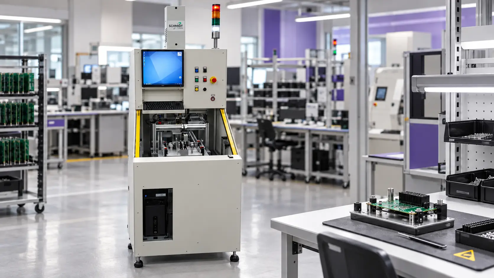
Seica Automation MODULO Concept for Press-Fit Pin and Connector Assembly
Developed by Seica Automation, one of Sinerji’s solution partners, the MODULO Concept is a modular platform that can be configured for different assembly and automation requirements in electronics manufacturing. Its configuration for press-fit applications enables pins and connectors to be pressed into printed circuit boards in a controlled and repeatable manner.
Controlled Pressing with MODULO Concept
MODULO Concept uses programmable servo-press technology for press-fit pin and connector assembly. The insertion movement can be programmed for different connector types and heights according to the application. This reduces the need for mechanical height adjustments and provides greater flexibility in production scenarios that include different connectors on the same product.
Closed-loop force and distance measurement helps ensure that the insertion process remains within the defined process tolerances. By monitoring force changes and travel during insertion, the system generates measurable process data that indicates whether the connection was completed as expected. Advanced operating modes such as Delta Force control support detection of the point at which the connector housing reaches the PCB surface and help complete the insertion process in a controlled manner.
When preparing a MODULO Concept project, the connector locations on the board, assembly sequence, access conditions, required insertion force, and PCB support fixture are evaluated together. For products with multiple press-fit operations, the press tool, process parameters, and inspection criteria can be defined separately for each connection. The system can be configured either as a stand-alone production cell or for integration into an automated production line and the existing traceability infrastructure.
The Role of the Press-Fit Station in the Production Line
With a modular automation approach, it is useful to consider the entire board flow rather than focusing only on the insertion station. Steps such as connector preparation, board transport, product identification, and transfer to the next inspection stage help define the required project scope. The equipment responsible for each operation and the scope included in the proposal must be clearly defined.
Electrical test and IC programming solutions can also be reviewed when developing the post-assembly inspection plan. Selection of the appropriate test method depends on the board circuitry and the product’s acceptance requirements. Defining separately which information will be provided by press-fit process control and electrical testing makes the role of each stage in production easier to understand.
Frequently Asked Questions About Press-Fit
Can Every Connector Be Installed Using Press-Fit?
No. For a connector to be installed using press-fit, its contact pins must be specifically designed for this method. The PCB’s hole structure, tolerances, plating quality, and mechanical strength must also meet the relevant assembly requirements. Moving from a soldered design to a press-fit application should therefore not be treated as a simple change in assembly method. Product design, board construction, and process conditions must be evaluated together.
Can the Same Pressing Recipe Be Used for Every Product?
No. The force, speed, stroke, insertion depth, and support structure used in the press-fit process must be defined according to the product. When different connector types, pin geometries, PCB thicknesses, or board revisions are involved, the suitability of the same parameters must be revalidated. The correct approach is to establish a validated process window for each product or product family.
Does the Force Curve Replace Electrical Testing?
No. The force curve is extremely valuable for monitoring insertion behavior during assembly and identifying process deviations. However, this data alone does not verify the product’s complete electrical performance. Electrical testing, mechanical inspection, and any additional quality-verification steps that may be required should be addressed under a separate plan. The correct approach is to use force-curve monitoring as one part of the product-validation process.
Should You Choose a Semi-Automatic or Fully Automatic Inline System?
This decision should be based on production volume, product variety, staffing model, loading method, traceability expectations, and the configuration of the existing line. Semi-automatic solutions may be sufficient for flexible production scenarios with low or medium volumes. For higher-volume, repetitive production that requires traceability, fully automatic inline systems may provide a more efficient solution. The most appropriate choice is made by comparing sample process scenarios prepared for the same product.
What Are the Most Common Risks in Press-Fit Assembly?
The principal risks include:
- Pin bending or deformation
- Connector misalignment
- Damage to the PCB hole structure or plating
- Localized stress, cracking, or deformation of the board
- Insufficient or excessive insertion force
- Incorrect insertion depth
- Process parameters that are incompatible with the product
These risks can be reduced significantly through appropriate equipment selection, correct fixture design, and process validation.
Why Are Pilot Production and Sample Validation Necessary?
Pilot runs conducted before volume production make it possible to validate both the process parameters and the compatibility between the product and materials. At this stage, force curves can be reviewed, assembly quality can be assessed, the necessary electrical and mechanical tests can be planned, and operator and equipment preparation can be completed. This substantially reduces the likelihood of quality problems, downtime, and rework during volume production.
Can Traceability Be Established for Press-Fit Connections?
Yes. With the appropriate equipment and software infrastructure, process data from insertion cycles can be recorded. The force curve, cycle result, product information, date and time, and operator or machine data provide important advantages for quality assurance and retrospective analysis. Traceability is particularly important in automotive, industrial electronics, and other applications that require high reliability.
What Should Be Checked Before Introducing Press-Fit Technology?
The following areas should be evaluated together for a successful transition:
- Press-fit compatibility of the connector
- PCB hole structure and tolerances
- Selection of suitable equipment and tooling
- Support-fixture design
- Validation of process parameters
- Quality-control and test plan
- Traceability requirements
- Production volume and level of automation
This evaluation should be treated as comprehensive process planning rather than simply as an equipment-selection exercise.
How Is the Right Solution Determined for Your Press-Fit Application?
The right solution is determined according to the product structure, manufacturing targets, quality expectations, and investment approach. A semi-automatic system may be more appropriate for flexible, low-volume production in some applications, while a fully traceable inline automatic solution may be the better choice for other projects. The product, process, and manufacturing structure should therefore be evaluated together to determine the most appropriate equipment and process-control approach.
Why Are Fixturing and PCB Support Critical in the Press-Fit Process?
The force applied during insertion is transferred directly to the PCB. If the board is not adequately supported, localized flexing, deformation, or structural damage may occur. For this reason, the lower support fixture used in press-fit applications is critical not only for holding the board, but also for distributing the insertion force correctly. Proper support is especially important for thin PCBs, applications with multiple connectors, and designs that contain sensitive areas.
Commissioning, Maintenance and Technical Support
Preparing a press-fit system for production does not end with machine installation. The suitability of the PCB support fixture and press tooling for the application must be checked, insertion parameters must be validated through sample assemblies, and acceptance criteria must be established. Training operators to load boards, perform product changeovers, and respond to nonconforming assemblies is also an important part of the transition to volume production.
After production begins, tool wear, fixture condition, and changes in force–displacement data should be monitored regularly. Planned maintenance and controlled recipe management help preserve the assembly conditions. Learn more about Sinerji’s technical service and engineering services, and work with our team to define the appropriate scope of services for your installation, operator training, maintenance, and production-support requirements.
Find the Right Solution for Your Press-Fit Production with Sinerji
Whether you are setting up a new press-fit production line or improving an existing assembly process, the selected system must be compatible with your PCB, connector, and daily production flow. You can evaluate Sinerji’s solutions according to your production capacity, product variety, and automation expectations while addressing fixture, process-control, and traceability requirements alongside equipment selection.
If your project is still in the design stage, you can share your PCB drawings and connector information with our team. If you want to improve an existing production process, you can share the assembly issues you are experiencing. To review your application requirements together and identify the press-fit solution best suited to your production, contact our team today.